Using Your Udamonic Controller
Choosing a Power PACK
|
A 9VDC -12V DC power supply is recommended.
Choose a 9VDC or 12VDC power pack in the range 0.5A to 3A for a Single Controller or Momentum Controller, and in the range 1A to 3A for a Duo controller. Note that if you run sound-equipped locomotives, your sound decoders may require a 12V DC supply for operation.
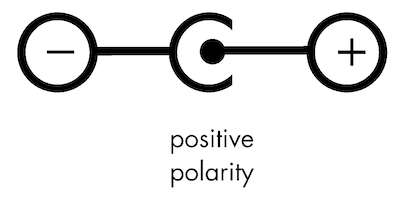
The exact current rating required depends on your chosen scale, how many locomotives you run at the head of your trains, and whether they are sound-equipped. A typical locomotive motor draws between 100 mA and 350 mA, depending on the manufacturer and scale. Some sound-equipped locomotives can draw twice that amount. If you run single or double-header trains, a 500 mA (0.5A) power pack is sufficient. If you run multiple (3-5) locos on your trains, go for a 1A-2A power pack. The power pack must have a 2.5 mm jack, with the centre pin positive. (Some power packs have 2.1 mm jacks and will not connect to your controller.) |
Note that Hornby-brand power packs (made in China) can output over 20V despite being labelled 12V. They rely on the Hornby controller to pull the voltage down to 12V. Do not use Hornby power packs with this controller as they will cause permanent damage instantly.
|
Mounting
|
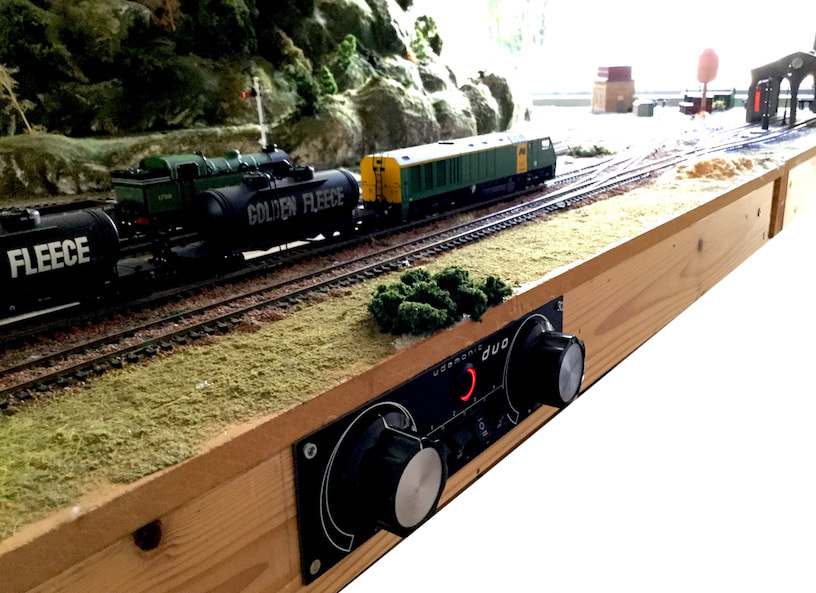
Your controller is designed to be mounted into a control panel, into the side of your layout, or in the corner of a layout baseboard. The controller has four mounting holes, 3 mm in diameter, suitable for M3 screws. The mounting holes are 5 mm in from each edge, and 5 mm from the required clearance cutout. The holes are electrically connected to the controller ground (GND) shield.
The controller is intended to be supported at all four mounting points. Mounting the controller along one edge only may cause mechanical stress over time. Do not over-tighten the screws as excessive force can damage the circuit board. Firm, but not gorilla force. |
The dimensions for the required rectangular cutout are shown on the back on your controller.
Note there is a row of five holes labelled J1 on the back of your controller. This is used during the build of the controller for configuring and testing the onboard computer. DO NOT CONNECT anything to J1. It is not for general use, and making undetermined connections to it can damage your controller.
Connecting
Connecting your Udamonic controller is easy. Watch this video to see how quick and simple it is.
|
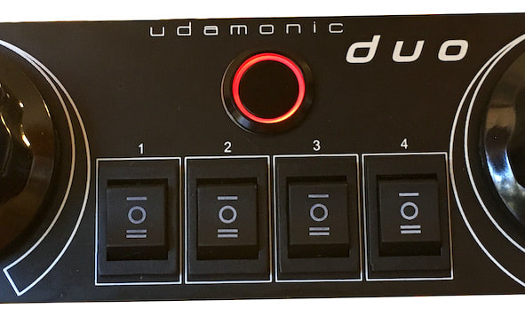
The Duo has four outputs, corresponding to each of the front panel switches. The outputs are labelled 1 to 4, corresponding to switches 1 to 4. These outputs should be connected to sections of track that are isolated from each other. The switches can be used to connect a track section to control I, control II, or isolated (O). Visit the example layouts page which shows how the four switch sections might be used operationally.
|
Using Your Controller
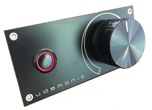
Push the power button to turn your controller on. The controller has an onboard single-chip computer that runs the show, and the red LED is controlled by the computer. The LED flashes once at startup to indicate that startup is complete, and then stays on indicate that the computer is powered and running. The controller is ready to use.
To power down your controller, press the power button so that it disengages. To perform an emergency stop, simply use the power button to turn off the controller.
To power down your controller, press the power button so that it disengages. To perform an emergency stop, simply use the power button to turn off the controller.
Powering Accessories
There is no "accessory power" output provided. This is a deliberate design choice as your accessories should be independently powered. Many layouts have a lot of accessories, and the current they draw just limits the current that would be available for your locomotives. Also, an accessory fault or excessive current draw would trigger the controller's short-circuit protection, causing the trains to stop. So for your accessories, just pick up a separate DC adaptor, and power them that way. It's a much better way to do it.
Safety Features
Your controller has inbuilt short circuit protection, over voltage protection and under voltage protection. It also has thermal shutdown in instances where excessive current may cause the controller to overheat. In all of these situations, the output of the controller is disabled for the duration of the fault. As soon as the fault is corrected, normal operation will resume instantaneously.
|
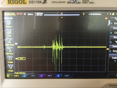
All DC motors generate voltage transients, typically 16V-24V. Older motors or motors with worn brushes or gears can generate transients up to 50V when running off a 12V controller. These can severely damage or kill modern electronics. DCC modules are particularly susceptible to this, and can be killed by older model engines.
Udamonic controllers incorporate transient voltage suppression and supply very clean and noise-free power to the track. Any motor transients (spikes) over 14V are completely removed from the track. This is good for your controller, and good for your engines. |
Troubleshooting
Each Udamonic controller is fully tested when it is built, and tested again before it is shipped. They're pretty robust. If your controller appears to be not working, the first thing to do is to try on on a test track independently of your layout. Invariably, controller "faults" turn out to be wiring faults. The controller is designed to shut itself down if it detects a wiring fault or short circuit.
"... it works in one direction but not the other..."
The controller uses the same electronics for both directions, so if it works in one direction then it will work in both directions. If it doesn't, then there is a wiring fault (possibly a partial short) that is showing up in one direction. The controller is detecting a partial short in a particular direction and shutting itself down.
"... but my other controllers work just fine..."
Many controllers don't have good short circuit or overload protection. If there is a partial short, then most controllers will struggle against it. Long term, this can cause stress for the electronics in those controllers. The Udamonic controllers have short circuit and overload protection with very fast response times (in the order of microseconds). So if they detect a partial short, they will shut themselves down "instantly" in response to it. This is what they are designed to do. So check your layout for a possible short.
"... the controller works with most of my engines but not with some of them..."
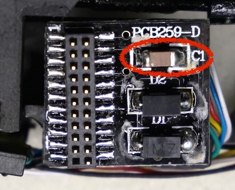
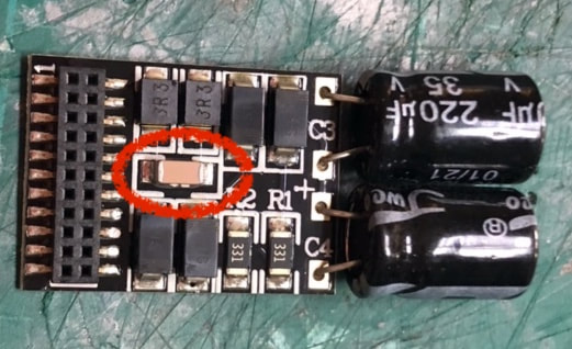
Some "DCC ready" locomotives have blanking ("dummy") modules that have a filter capacitor on them. Older controllers just provide flat DC voltage. The motors kick back electrical transients as their magnetic fields change as they rotate. It can cause interference with other appliances, and it's also really bad for the motors themselves if they are coreless (and most/all modern motors are coreless). So some loco manufacturers have started putting in filters to remove the transients. It works just fine with old-style DC controllers. But with high-frequency DCC modules and my controllers, it simply filters out the pulses trying to drive the motors. All the motors get is zero volts. My controllers take care of the transients, so the filter incorporated into the dummy modules is unnecessary.
You don't need to modify your loco, all you need to do is modify the dummy module and remove the capacitor (it's the little brown thing marked as C1 in the first photo) to disable the filter. Removing the capacitor is the easiest fix. If you don't feel comfortable making the modification, just pick up a dummy module that doesn't have a capacitor. They are out there. (Thanks to Peter Wright and David Carling for highlighting this issue and testing the fix.)
"... it's something else..."
If you're still having problems, try the controller on a test track, with a few engines. If it doesn't work, get in touch. If it works fine on your test track, there's a wiring fault and/or partial short in your layout (even if your other controllers "work just fine").
Any questions, please don't hesitate to get in touch.
Sound-Equipped Locomotives
Note: a 12VDC adaptor may be required for DCC sound-equipped locomotives due to way the sound modules are designed. Typically, they require 8V-9V for their power, and use the range above that to determine the desired speed. In other words, for a sound decoder, 8V-9V turns them on, but the engine is stopped.
Sound decoders are quirky beasts. Sound decoders "read" the voltage on the track, and use their onboard computer to control the motor directly using their own PWM. In this instance, the Udamonic controller is not driving the motor directly. How a sound decoder controls the motor under non-DCC operation varies greatly from decoder to decoder. Most sound decoders (for example, QSI) work fine with non-DCC control. But some sound decoders (such as Bachmann/Lenz) may exhibit odd behaviour with their default settings and may need their CV values changed/optimised for correct operation. Please refer to your decoder module manual for more information. (Note this is a characteristic of the sound decoders and not the Udamonic controllers.)
Also note that Bachmann engines come with a suppression capacitor fitted to remove electrical noise when the engines are used with old-style rheostat controllers. Bachmann (and others) actually recommend removing this capacitor if it is not required. See https://sites.google.com/site/markgurries/home/technical-discussions/decoder-motor-drive/motor-capacitors/bachmann-engines. With Udamonic controllers, Bachmann's suppression capacitor is unnecessary, and may affect the operation of the engine when used with Udamonic controllers. The capacitor can impact how the controller drives the motor. Udamonic controllers incorporate transient voltage suppression and supply very clean and noise free power to the track, so Bachmann's capacitor is not needed.

