CREATE : LEDS : Adding External LEDs
Basic LED Circuit
|
There are a lot of choices when it comes to LEDs. Which you choose doesn't particularly matter, so long as you take note of two important parameters. These are the maximum forward current that the LED can handle, and the forward voltage drop (Vf) of the LED.
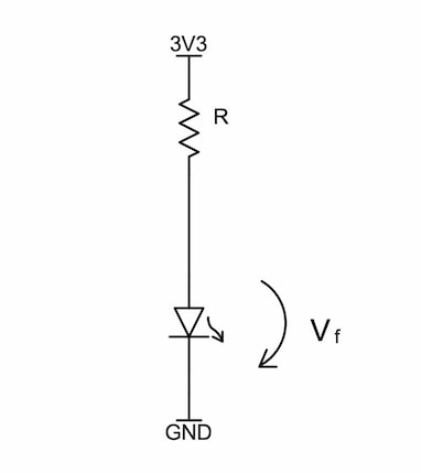
Exceeding the maximum forward current rating of the LED will damage or destroy the device. To limit the current flowing through the LED, we use a current-limiting resistor, and to calculate the value for this resistor, we need to know Vf. The basic circuit for any LED is shown at right. |
Adding a Power LED
First, let's looking at including a power LED driven by the 3V3 power rail. We'll choose the green LG R971 ChipLED made by Osram. This is a surface-mount device in a 0805 footprint, large enough to be hand solderable. This LED's datasheet indicates that it has a maximum forward current of 20 mA, and a typical forward voltage drop of 2.2 V. If the total voltage (V) across the resistor and LED together is 3.3 V, and the voltage across the LED is 2.2 V, then the voltage across the resistor must be:
Vr = V - Vf
= 3.3 V - 2.2 V
= 1.1 V
Using Ohm's Law, if we know the maximum current (20 mA) and voltage drop (1.1 V), we can calculate the minimum value required for the resistor:
R = V / I = 1.1 V / 20 mA
= 55 ΩAdding a Status LED
Let's choose a second LED, but this time a red one, such as the Osram LH R974 ChipLED. We might assume that we can just use the same value for the current limiting resistor, and we'd be wrong. It's important to always check the technical data, even for very similar devices. For while the forward current is the same as the green ChipLED, the forward voltage drop (Vf) is lower at 1.8 V. So, the voltage across the resistor for this ChipLED is:
Vr = V - Vf = 3.3 V - 1.8 V = 1.5 VWhile the maximum current this ChipLED can take is 20 mA, the maximum current that a PIC24 processor pin can output is 18 mA. Therefore, 18 mA is the maximum current we must use in our calculation.
So, our calculation for this current limiting resistor becomes:
So, our calculation for this current limiting resistor becomes:
R = V / I = 1.5 V / 18 mA = 83 ΩHad we assumed that the calculation was the same as for the green ChipLED and used a 55 Ω resistor, we could have damaged both the LED and the PIC24. While this may not cause immediate failure, over time it could reduce the operational life expectancy.
Reducing LED Power Consumption
Note that the values we calculated are the minimum resistor values we can use for the current limiting resistors, and they result in very bright LEDs. 18 mA and 20 mA are a big chunk of the total current available from a voltage regulator, particularly if you are using a regulator with relatively low output current.
If we increase the value of the resistors by a factor of ten (approximately) to be 560 Ω, then the current drops to a mere 2 mA for the power LED and 2.6 mA for the status LED. These LEDs will still be quite bright enough for their purpose, and will reduce our overall power consumption. By choosing the same value for both resistors, we reduce the number of different values required in our design. When producing systems commercially, this can have an impact on the overall manufacturing cost.
The power dissipated by the current limiting resistor for the green LED is calculated by:
P = V * I = 3.3 V * 2.6 mA = 8.6 mWTherefore, we need to select resistors above this power rating, which in practical terms, is 0.1 W or higher.
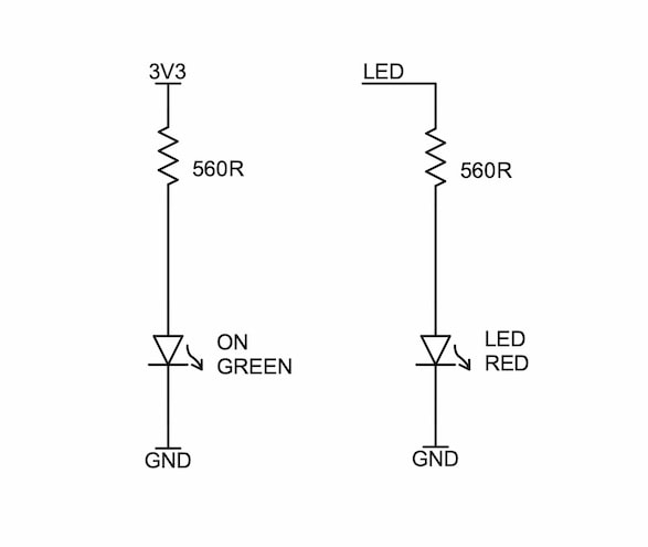
Our resulting schematic for the two LEDs is:
Our resulting schematic for the two LEDs is:
Toggling the LED
Let's assume we have connected the status LED to pin 1 of the Scamp. To control it, we need to make pin 1 an output:
1 output
To turn the LED on:
1 set
To turn the LED off:
1 clear


