CREATE : DISPLAYS : Adding a 7-Segment Display Module
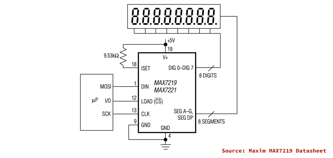
The MAX7219 (datasheet) is a display driver that interfaces to 7-segment numeric LED displays of up to 8 digits, bar-graph displays, or 64 individual LEDs. Included on-chip are a BCD code-B decoder, multiplex scan circuitry, segment and digit drivers, and an 8x8 static RAM that stores each digit. It uses a SPI interface to communicate with the host processor.
A number of commercial display modules using this chip are available, and this article looks at the requirements for interfacing to a Scamp3.
A number of commercial display modules using this chip are available, and this article looks at the requirements for interfacing to a Scamp3.
The basic schematic of these modules is:
Many 5V devices accept a logic high of 2.4V, making them compatible with the outputs of 3V3 systems. Unfortunately, the MAX7219 is not one of these devices. A logic high for the MAX7219 is a minimum of 3.5V. Therefore, we need to provide some level translation for the Scamp3's SPI signals. There are many ways of doing this. One of the simplest, particularly if you have a lot of signals to level-shift, is to use a 74HC244 buffer. The '244 has a wide operating voltage range of between 2V and 6V, and accepts a logic high input compatible with 3V3 logic, and gives an output high of 4.5V.
The basic schematic for interfacing a display module to a Scamp3 is:
The basic schematic for interfacing a display module to a Scamp3 is:
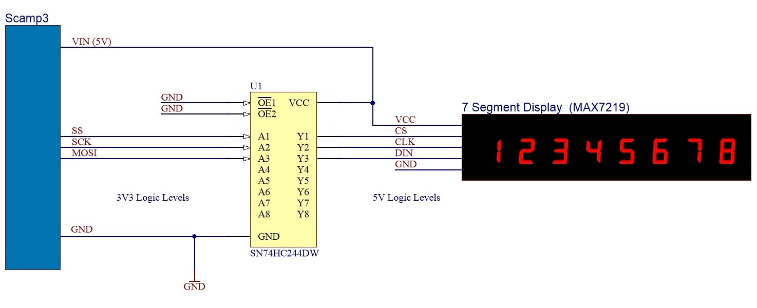
SS (Slave Select) is level shifted to become CS (Chip Select). SCK becomes CLK, and MOSI (Master Out Slave In) becomes DIN (Data In).
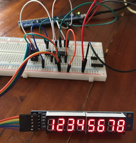
This can be put together quite quickly for prototyping on a breadboard.
This can be put together quite quickly for prototyping on a breadboard.
The following word will initialize the MAX7219 over the SPI interface. The MAX7219 is a write-only device. Therefore we can just drop the return value from any SPI transfers.
: init
16 spisize \ MAX7219 requires 16 bit transfers
spiclk- \ negative clock polarity
$0f00 spix drop \ MAX7219 test mode off
$09ff spix drop \ decode for all digits
$0b07 spix drop \ scan for all digits
$0c01 spix drop \ normal operation
;
This word will clear all digits:
: blank
8 for
i 1+ $100 * $f or spix drop
next
;
So at startup, execute the following words to begin using your display.
init
blank
The following word will turn on all LED segments for testing:
: teston
$0f01 spix drop
;
And to return to normal operation:
: testoff
$0f00 spix drop
;
This word will vary the intensity of the display:
: intensity ( n -- , sets intensity)
\ valid values are 0..15
$0a00 or spix drop
;
To use the intensity word:
0 intensity \ minimum intensity
15 intensity \ maximum intensity
The following words allow you to set individual digits on the display. They accept a value of 0 .. 9 off the stack.
: digit0
$0100 or spix drop
;
: digit1
$0200 or spix drop
;
: digit2
$0300 or spix drop
;
: digit3
$0400 or spix drop
;
: digit4
$0500 or spix drop
;
: digit5
$0600 or spix drop
;
: digit6
$0700 or spix drop
;
: digit7
$0800 or spix drop
;
For example to set digit 7 to display the value 3:
3 digit7
These two words take decimal values in the range 0..9999 and set the lower and upper digits respectively:
: displayL
dup #1000 /
dup $0400 or spix drop
#1000 * -
dup #100 /
dup $0300 or spix drop
#100 * -
dup #10 /
dup $0200 or spix drop
#10 * -
$0100 or spix drop
;
: displayH
dup #1000 /
dup $0800 or spix drop
#1000 * -
dup #100 /
dup $0700 or spix drop
#100 * -
dup #10 /
dup $0600 or spix drop
#10 * -
$0500 or spix drop
;
For example, to show 1234 5678 on the display:
1234 displayH 5678 displayL
As a final example, the following word performs a 60 second countdown in 100 msec increments:
: countdown
600 for
i displayL 100 ms
next
;