CREATE : GPIO : USING THE Udamonic 32-bit GPIO Module
|
The Udamonic 32-bit GPIO module (available from Apollo Controllers) uses two NXP PCA9555s (datasheet).
The module has two banks of 16 bits of GPIO (GPIO1 and GPIO2) that can user-configured over the I2C bus. Each bank is comprised of two 8-bit ports per PCA9555. Up to two GPIO modules may be added to your Scamp, giving you up to an additional 64-bits of GPIO. When connected to a Scamp, all the other Scamp pins on the main connector are still accessible. You can solder IDC connectors of your choice to the module. Note that the footprints for the connectors have an entire row of GND pins (highlighted with a white mask). This allows every alternating wire on a ribbon cable to be a shield. |
Schematic
| ||
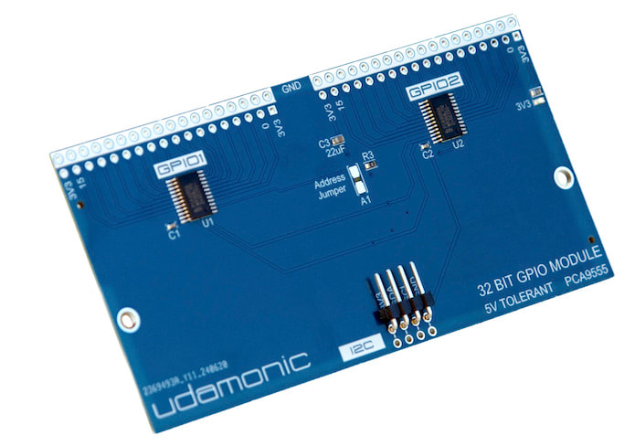
32-bit GPIO Module
|
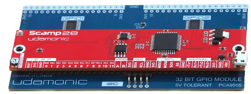
32-bit GPIO Module mated to a Scamp2e
|
Once the GPIO module is attached to your Scamp, use the modules word to scan for its presence. Each module will appear as two addresses in the address table.
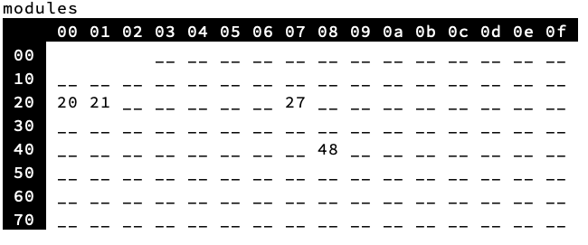
The default addresses are $20 and $21, each being one of the two PCA9555s. The address selection jumper on the PCB can be used to change the default addresses to $22 and $23, by creating a solder bridge across it.

|
Note
The PCB build (number 2369493A_Y11-240620 on the PCB) was fitted with a 0Ω resistor instead of a 1M resistor for R3 by the board manufacturer. If you are changing the default address by bridging the address jumper, you MUST desolder and remove R3. Failing to do so will cause a short. 
|
|
Defining the addresses in Forth
$20 constant GPIO1
$21 constant GPIO2
Configuring
The PCA9555 has eight registers, two for each port.
0 constant input0
1 constant input1
2 constant output0
3 constant output1
4 constant polarity0
5 constant polarity1
6 constant config0
7 constant config1
Registers may be written individually, or multiple registers may be written sequentially by sending bytes over the I2C bus. The PCA9555 automatically increments to the next register on a successful send.
The Input Port Registers are read-only. They reflect the incoming logic levels of the pins, regardless of whether the pin is defined as an input or an output. Writes to these registers have no effect.
Writes to an Output Port Register will set or clear the logic levels of the pins defined as outputs. Bit values in this register have no effect on pins defined as inputs. Reads from this register return the value that is in the flip-flop controlling the output selection, not the actual pin value.
The Polarity Inversion Registers allows the user to invert the polarity of an Input Port register data. If a bit in this register is set (written with ‘1’), the corresponding Input Port data is inverted. If a bit in this register is cleared (written with a ‘0’), the Input Port data polarity is retained.
The Configuration Registers and controls the direction of the I/O pins individually. If a bit in this register is cleared, the corresponding port pin is enabled as an output with high-impedance output driver. If a bit in this register is set, the corresponding port pin is enabled as an input. At reset, the I/Os are configured as inputs with a weak pull-up.
(0 = output, 1 = input)
Registers may be accessed from within your words, or directly from the command line.
The following words configure each PCA9555:
: init1 ( n n -- , configures GPIO1 ports 0 and 1 )
start
GPIO1 write drop
config0 send drop
send drop
send drop
stop
;
: init2 ( n n -- , configures GPIO2 ports 0 and 1 )
start
GPIO2 write drop
config0 send drop
send drop
send drop
stop
;
To configure the module for 16-bits of input on GPIO1 and 16-bits of output on GPIO2:
$ff $ff init1
0 0 init2
The following words read back the configuration from the two PCA9555s:
: getconf1 ( -- n n , read back two config bytes from GPIO1 )
start
GPIO1 write drop
config0 send drop
repstart
GPIO1 read drop
receive ack
receive nack
stop
swap
;
: getconf2 ( -- n n , read back two config bytes from GPIO2 )
start
GPIO2 write drop
config0 send drop
repstart
GPIO2 read drop
receive ack
receive nack
stop
swap
;
To read inputs from the two PCA9555s:
: getin1 ( -- n n , read back two input bytes from GPIO1 )
start
GPIO1 write drop
input0 send drop
repstart
GPIO1 read drop
receive ack
receive nack
stop
swap
;
: getin2 ( -- n n , read back two input bytes from GPIO2 )
start
GPIO2 write drop
input0 send drop
repstart
GPIO2 read drop
receive ack
receive nack
stop
swap
;
To use:
$ff $ff init1 \ configure GPIO1 as inputs
$ff $ff init2 \ configure GPIO2 as inputs
getin1
getin2