udamonic.com
  • Start
    • What is a Scamp?
    • Getting Started
    • Getting Started (Windows)
  • Learn
    • What is Forth?
    • Arithmetic
    • The Stack
    • Creating Words
    • Compilation Tricks
    • Decompilation
    • Comments
    • Characters and Strings
    • Accessing Memory
    • Constants, Variables and Values
    • Flow Control
    • Loops
    • Data Structures
    • Doubles, Triples and Quads
    • FlashForth Dictionary Reference
    • Scamp Dictionary Reference
  • Extras
    • Interrupts
    • Timers
    • Multitasking
    • Delays and Tick Count
    • Processor Words
    • Starting up with turnkey
    • Changing the Prompt
    • Formatting Text on Screen
  • Interfacing
    • Using the LED Array
    • Temperature Sensor
    • Input/Output
    • Analog Input
    • Serial >
      • Serial Communication
      • Scamp Serial Comms
      • Scamp2 UART Pins
    • I2C >
      • I2C Overview
      • I2C Commands
    • SPI
    • PWM
    • Peripheral Pin Select
    • Input Capture
    • Digital Signal Modulator
    • DataFlash
    • RS485
  • Create
    • Scamp Projects on Youtube
    • Prototyping >
      • Protoboards
      • Fabricating PCBs
      • Soldering
    • GPIO >
      • Adding Extra GPIO
      • 32-bit GPIO Module
      • Adding a Low Side Switch
    • Sensing >
      • Measuring Temperature
    • LEDs >
      • Adding LEDs
      • LED arc-welder effect
    • Memory >
      • Adding MRAM
      • AT24C256 EPROM Driver
    • Displays >
      • Adding a 7 Segment Display
      • Adding a Touch LCD
      • Touch LCD GUI
      • Game of Pong
    • FizzBuzz
    • Model Train Control
    • Adding a Real Time Clock
    • 1-D Pacman
  • Resources
  • Buy
  • Consulting
  • About

CREATE : PROTOTYPING : Protoboards
​

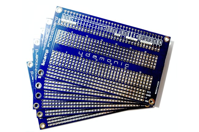
The protoboards can be used for permanent prototyping of your projects. They can be used in the same manner as a breadboards. There is a central prototyping area, suitable for DIP packages and other components. At the bottom of the protoboard are power rails, directly connected to the corresponding power rails of the Scamp. At the top of the protoboard, a connector provides access to the Scamp signals and power pins. The Scamp connects to the horizontal row of pins at the top of the protoboard. Note that this connector is not soldered, so that you can change the orientation if you so choose. ​Mount your Scamp either horizontally or vertically. 
Picture
​You can order protoboards with your Scamp. Or you can order a bulk pack separately on Tindie.
Shop Protoboards

Scamp3 Blue Protoboard
​

The Scamp3 protoboard is intended for use with Scamp3 computers. See Ken Merk's video (right) introducing the protoboard.

Note there are pin differences between the Scamp3 and Scamp3e computers, so select the protoboard that is right for your Scamp. (The Scamp3 has a GND pin where the Scamp3e has an RS485 signal.)


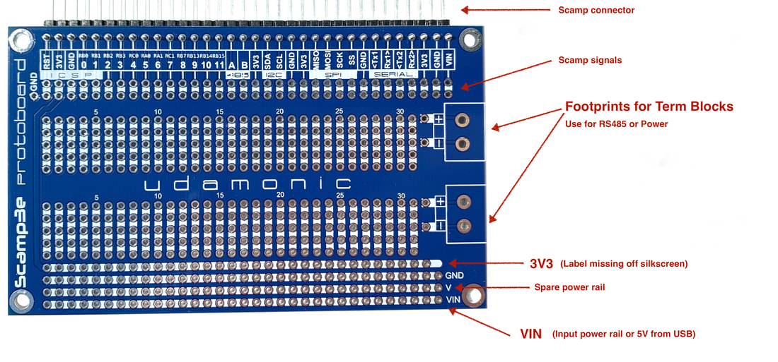
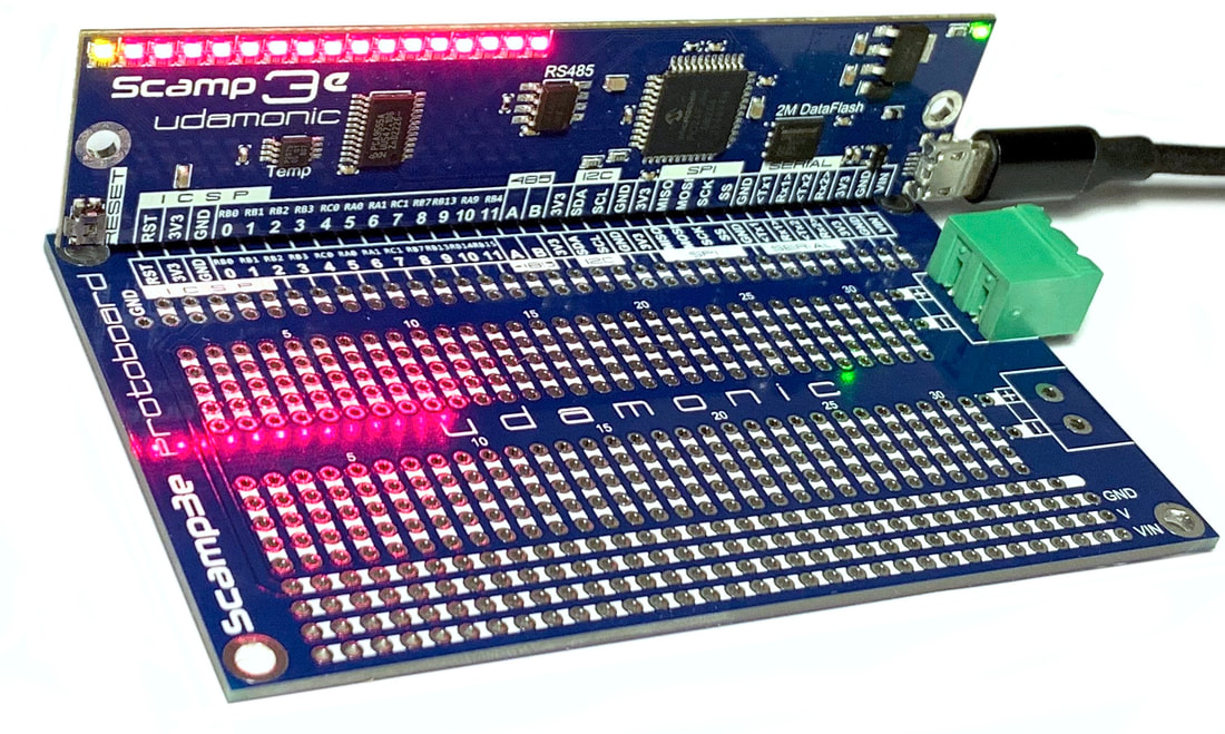
Scamp3e Blue Protoboard
​

The Scamp3e protoboard can be used with Scamp2e, Scamp3 and Scamp3e computers. Please note that the 3V3 rail is missing its label during to an error in the first production run. This will be corrected in future runs. This rail IS connected to 3V3 on the Scamp - do not wire it to another voltage source. 

The Scamp3e protoboard has two footprints for 2 pin terminal blocks, with 5.08 mm pin spacing. These may be used as general purpose connectors, power supply connectors or RS485 connectors. 
Picture

BlackBoard
​

The BlackBoard protoboard features footprints for SO8, SO16 and SOT-23 surface mount components, as well as an area for conventional through-hole prototyping. The BlackBoard also has three TERM blocks, a DB-9 connector, an IDC16 footprint and a DC socket for an external 5V-12V power supply.
Picture
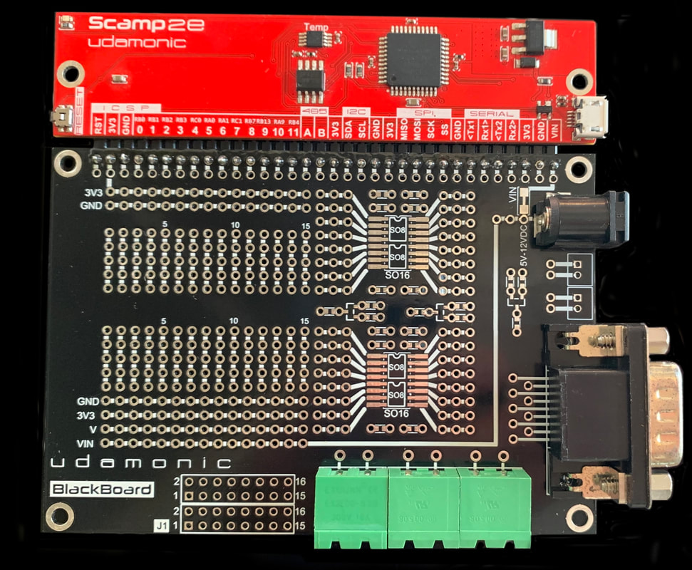
Scamp2e with a BlackBoard
Picture
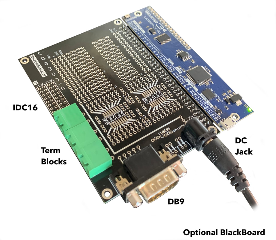
Scamp3e with a BlackBoard
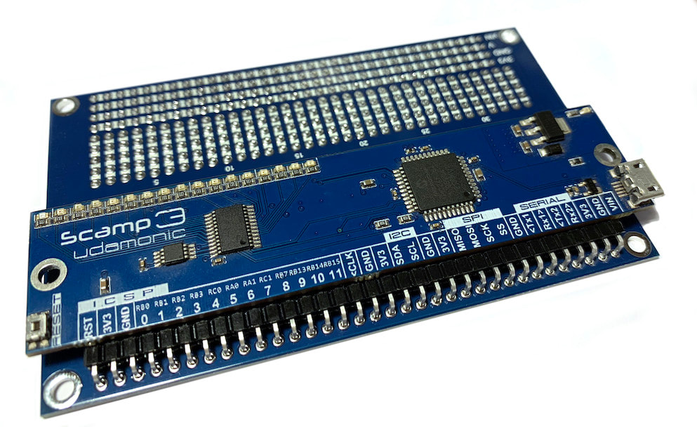
Orientation
​

Replace the right-angle pin header with a vertical header, and you can mount your Scamp at right angles to the protoboard if this better suits your application.

By reversing the connector, the Scamp can be mounted on the underside of the protoboard to save space.

To make this change easier, the protoboards are supplied with the header not soldered in place. 
Picture
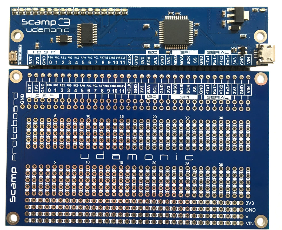
Horizontal (Inline) Mount
Picture
Right-angle Mount
Picture
Underside Mount
Site powered by Weebly. Managed by Hostwinds
  • Start
    • What is a Scamp?
    • Getting Started
    • Getting Started (Windows)
  • Learn
    • What is Forth?
    • Arithmetic
    • The Stack
    • Creating Words
    • Compilation Tricks
    • Decompilation
    • Comments
    • Characters and Strings
    • Accessing Memory
    • Constants, Variables and Values
    • Flow Control
    • Loops
    • Data Structures
    • Doubles, Triples and Quads
    • FlashForth Dictionary Reference
    • Scamp Dictionary Reference
  • Extras
    • Interrupts
    • Timers
    • Multitasking
    • Delays and Tick Count
    • Processor Words
    • Starting up with turnkey
    • Changing the Prompt
    • Formatting Text on Screen
  • Interfacing
    • Using the LED Array
    • Temperature Sensor
    • Input/Output
    • Analog Input
    • Serial >
      • Serial Communication
      • Scamp Serial Comms
      • Scamp2 UART Pins
    • I2C >
      • I2C Overview
      • I2C Commands
    • SPI
    • PWM
    • Peripheral Pin Select
    • Input Capture
    • Digital Signal Modulator
    • DataFlash
    • RS485
  • Create
    • Scamp Projects on Youtube
    • Prototyping >
      • Protoboards
      • Fabricating PCBs
      • Soldering
    • GPIO >
      • Adding Extra GPIO
      • 32-bit GPIO Module
      • Adding a Low Side Switch
    • Sensing >
      • Measuring Temperature
    • LEDs >
      • Adding LEDs
      • LED arc-welder effect
    • Memory >
      • Adding MRAM
      • AT24C256 EPROM Driver
    • Displays >
      • Adding a 7 Segment Display
      • Adding a Touch LCD
      • Touch LCD GUI
      • Game of Pong
    • FizzBuzz
    • Model Train Control
    • Adding a Real Time Clock
    • 1-D Pacman
  • Resources
  • Buy
  • Consulting
  • About