Using Input and Output
|
Your Scamp computer includes words to configure and read/write individual general-purpose IO (GPIO) pins. A GPIO pin can be configured as an input or output. Inputs can optionally have pullup or pulldown resistors activated. Outputs can optionally be configured as open-drain.
There is a bug in Scamp3/3e firmware versions v1.8 and earlier, where the reference oscillator output (REFO) is enabled for pin 9, when it shouldn't be. That is overriding all other functions associated with that pin. The following word will disable the REFO output, and all functions associated with pin 9 will work from then on.
: REFOoff |
|
Input
All pins can be configured as digital inputs.
|
|
|
To configure a pin as a digital input, first type the pin number followed by the word input. For example, to make pin 7 an input:
7 input
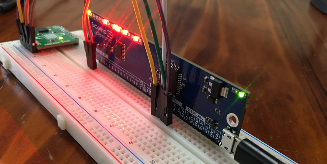
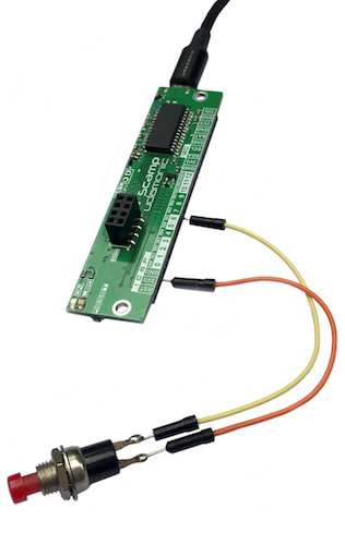
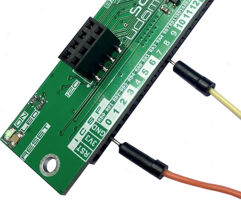
Connecting a switch is very simple. One side of the switch is connected to GND and the other side of the switch is connected to a pin, in this case pin 7:
|
|
If a pin is connected to a switch, it will require an internal pullup resistor to be activated. When the button is pressed, the input is connected to ground (0), otherwise the input is open circuit. We will need a pullup resistor activated to make sure the input is high when the button isn’t pressed. The switch word configures the pin as an input and activates an internal pullup resistor with one command:
7 switch
All inputs can be configured as switch inputs, except for the Scamp2e's pin 10. Each pullup input consumes typically 0.3 mA to 0.5 mA when enabled. To disable the pullup resistor, just configure the pin as an input.
For both a digital input or a switch input, the state of the pin is read using the get word. For example, to read the state of pin 7:
For both a digital input or a switch input, the state of the pin is read using the get word. For example, to read the state of pin 7:
7 get
If the input to pin 7 is high, then get will return 1 to the stack, otherwise it will return 0. Since anything not 0 is considered true in Forth, the result from get can be used directly by conditional words such as if. When using switch, a button press returns a 0, while no press returns a 1.
Let’s create a simple program to configure the pin, then continuously read the push button and if it is pressed (input is 0), turn the LED on:
: light ( -- , turn LED on when button is pressed )
7 switch ( configure pin 7 as switch input with pullup )
begin
7 get ( read state of button, return 0 if pressed )
if ( true if button not pressed )
ledoff
else ( button has been pressed )
ledon
then
key? ( repeat until a key is pressed )
until
;
The word pulldown activates a pulldown resistor for a given input pin. Pulldown resistors can be activated for all inputs. The word pulldown is used in conjunction with input or switch. To make pin 7 an input with a pulldown resistor enabled:
7 input 7 pulldown
Note that the input word deactivates both pullup and pulldown resistors, so the word pulldown must follow input. To activate both pullup and pulldown resistors for pin 7:
7 switch 7 pulldown
|
|
Note that pulldown is not available on the Scamp2e as the PIC24FJ32GB204 does not have internal pulldowns for GPIO.
Note that there is no internal pulldown for pin 11 on the Scamp3 or 3e, and no pullup on pin 11 on the 3e. This is a bug with the Microchip silicon.
|
|
Output
To configure a pin as an output, place the pin number on the stack and use the word output. For example, to make pin 3 an output:
3 output
|
|
All pins, except processor pin RA4, can be configured as output. (RA4 is input only - this is a limitation of the PIC24 processor.) On the Scamp2e, RA4 is mapped to pin 11.
|
|
Once configured as an output, the pin can be driven high or pulled low. A high is nominally 3.3V and a low is 0V. Each pin can source or sink 18 mA. Exceeding 18 mA may permanently damage your Udamonic computer.
To send pin 3 high:
To send pin 3 high:
3 set
To send pin 3 low:
3 clear
The word out will drive an output high or low depending on the state of the second-most top entry. Any value that is not 0 is treated as a 1. The top of the stack specifies the pin to be driven. For example, if pin 3 is an output:
0 3 out
will send pin 3 low, while:
1 3 out
will drive it high. out is used with words that place a bit value on the stack. For example, let's say that pins 5 and 7 are both inputs. We want to drive pin 3 high if either inputs 5 and 7 are high, otherwise pin 3 should be low. We read the two inputs, or them together, and then use out to send the result to pin 3:
5 get 7 get or 3 out
|
|
There is a bug in firmware versions 1.8 and earlier, where the set word does not work for pin 7. The workaround is to create a word that will set pin 7 manually:
: set7 Firmware v1.9 corrects this bug.
|
|
Learn : Interfacing : Input and Output