|
|
There is a bug in Scamp3/3e firmware versions v1.8 and earlier, where the reference oscillator output (REFO) is enabled for pin 9, when it shouldn't be. That is overriding all other functions associated with that pin. The following word will disable the REFO output, and all functions associated with pin 9 will work from then on.
: REFOoff |
|
The Scamp2, Scamp3 and Scamp3e have 6 PWM channels (channels 1 through 6), each capable of generating waveforms with up to 16 bits of resolution. The Scamp2e has 5 channels of PWM (1 through 5). Channels can be mapped to most pins, giving you flexibility in your application. PWM can be used for motor control, generating audio tones, or producing an analog output.
|
On a Scamp1/Scamp2, pins 0 ... 3, 5, 6, 9...12 can be assigned to PWM channels. Essentially, the same pins that support analog input (white background) also support PWM, with the addition of pin 9. Pins 4, 7 and 8 do not support PWM on a Scamp1/Scamp2.
|
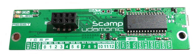
Scamp1 - pins with white background (plus pin 9) support PWM
|
|
On a Scamp3, all 12 pins (no limitations) can be assigned to PWM channels.
On the Scamp2e and Scamp3e, pins 10 and 11 do not support PWM. Use pins 0..9.
|
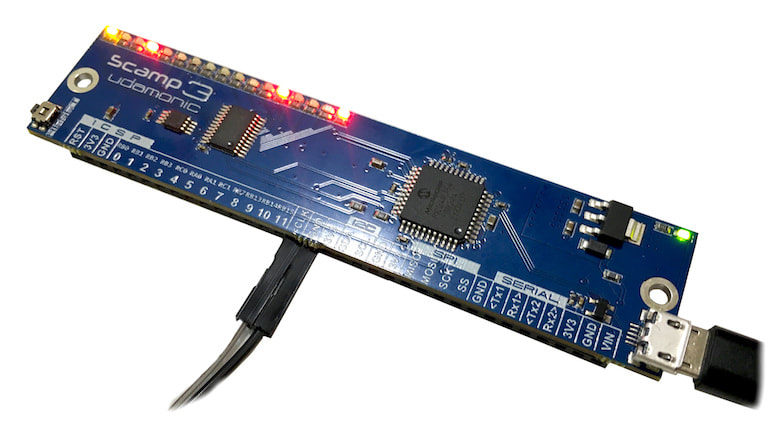
Scamp3
|
About Pulse Width Modulation
Consider these square waves:
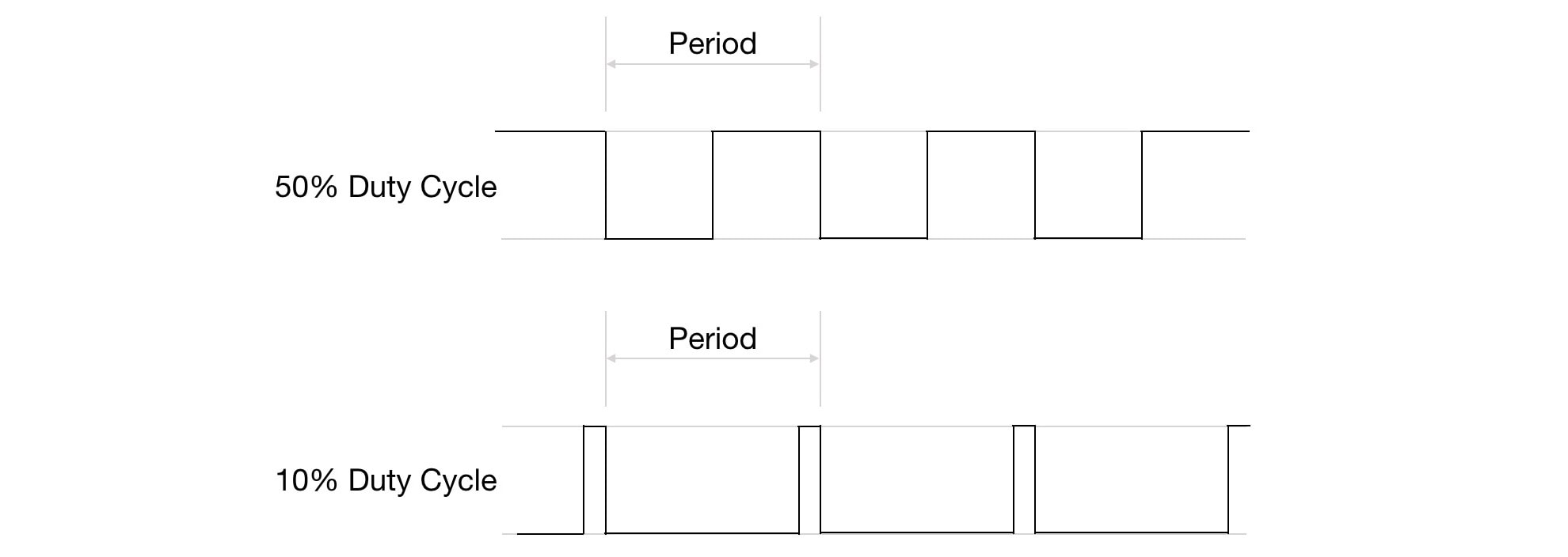
In the first square wave, the width of the high is equal to the width of the low, so this wave is said to have a 50% duty cycle. In other words, it is high for exactly half the cycle. Now, if the amplitude of this square wave is 3.3 V, the average voltage over the cycle is 1.65 V. It is as though we had a constant voltage of 1.65 V. The second wave has a 10% duty cycle, which means that the average voltage over the cycle is 0.33 V
A low-pass (averaging) filter on the PWM output will convert the pulses to an analog voltage, proportional to the duty cycle of the PWM signal. By varying the duty cycle, we can vary the analog voltage.
PWM can be used (with appropriate interface hardware) to drive motors, generate audio tones, fade LEDs, or any other application that requires an output more sophisticated than simple on/off.
PWM can be used (with appropriate interface hardware) to drive motors, generate audio tones, fade LEDs, or any other application that requires an output more sophisticated than simple on/off.
Selecting an Output Pin
Your Udamonic computer has 6 PWM channels. Any pin can be used for PWM on a Scamp3. On a Scamp1/Scamp2 all pins with the exception of pins 4, 7 and 8, can be allocated to any PWM channel. Supported channels are channels 1 through 6.
The word pwm will assign a PWM channel to a pin. The format is pin channel pwm. For example, to assign pin 2 to PWM channel 6:
The word pwm will assign a PWM channel to a pin. The format is pin channel pwm. For example, to assign pin 2 to PWM channel 6:
2 6 pwm
It is possible (and allowed) to have the same channel assigned to multiple pins if your application requires it. For example, to assign channel 5 to both pins 2 and 3:
2 5 pwm
3 5 pwm
The signal generated by PWM channel 5 will be output on both pins. This can useful if you want to drive an external circuit with a pin, and monitor the PWM values using an oscilloscope connected to second pin.
Setting the Period
The word period takes two parameters from the stack, a period value and a channel number, and sets the period of that PWM channel. For example, to set the period of channel 2 to be $400:
$400 2 period
A period of $ffff gives a base frequency of 245 Hz. A period of 2 gives a base frequency of 5.3 MHz, but with only a 2 bit resolution.
Setting the Duty Cycle
The duty cycle for a given PWM channel is set by the word duty. duty takes a value and a channel from the stack. For example, to set the duty cycle for channel 2 to be $300:
$300 2 duty
For motor control, the duty cycle corresponds to the speed of the motor.
|
|
Note that the duty cycle value should always be less than period value for a waveform to be generated. If the duty cycle is equal to or greater than the period, the output will stay high.
|
|
|
Ken Merk has a great video on Scamp PWM.
|
|
Learn : Interfacing : PWM