Introduction to Serial Communication
[ Jump to Scamp Serial Comms ]
Serial communication involves the transfer of data over a single wire for each direction. All serial interfaces convert parallel data to a serial bit stream, and vice versa. The simplest form of serial interface is that of the Universal Asynchronous Receiver Transmitter, or simply just UART for short. They are termed asynchronous because no clock is transmitted with the serial data. The receiver must lock onto the data and detect individual bits without the luxury of a clock for synchronization. Because of this, UARTs are somewhat forgiving of timing errors.
Serial devices send data one bit at a time, so normal “parallel” data must first be converted to serial form before transfer. Serial transmission consists of breaking down bytes of data into single bits and shifting them out of the device one at a time. A UART’s transmitter is essentially just a parallel-to-serial converter with extra features. The essence of the UART transmitter is a shift register that is loaded in parallel, and then each bit is sequentially shifted out of the device on each pulse of the serial clock. Conversely, the receiver accepts a serial bit stream into a shift register, and then this is read out in parallel by the processor.
Serial devices send data one bit at a time, so normal “parallel” data must first be converted to serial form before transfer. Serial transmission consists of breaking down bytes of data into single bits and shifting them out of the device one at a time. A UART’s transmitter is essentially just a parallel-to-serial converter with extra features. The essence of the UART transmitter is a shift register that is loaded in parallel, and then each bit is sequentially shifted out of the device on each pulse of the serial clock. Conversely, the receiver accepts a serial bit stream into a shift register, and then this is read out in parallel by the processor.
UARTs actually predate semiconductor-based computers. In the early days of electrical communication, UARTs were mechanical devices with cogs, relays and electro-mechanical shift registers. To adjust a UART’s settings, you first picked up a wrench!
|
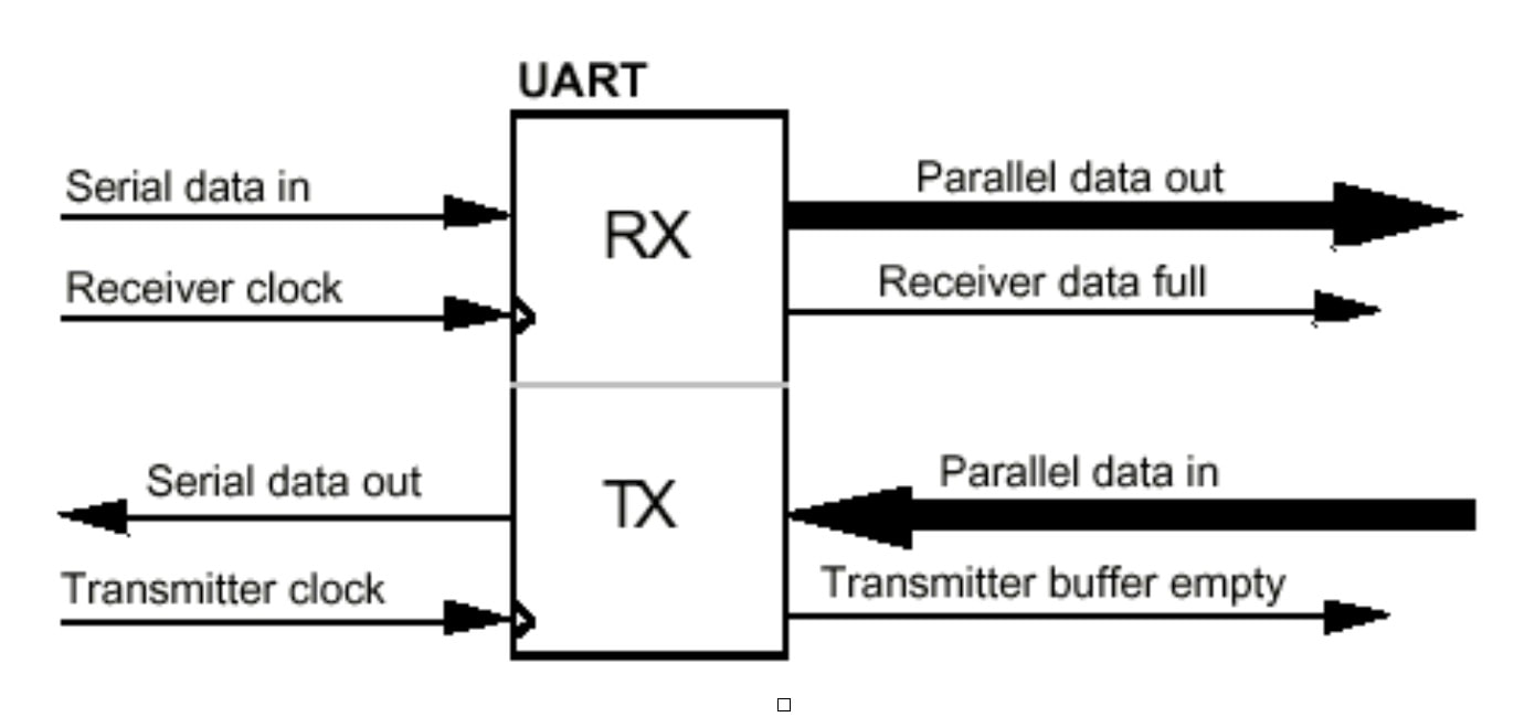
A UART consists of two sections, a receiver (Rx) that converts a serial bit stream to parallel data for the microprocessor, and a transmitter (Tx) that converts parallel data from a microprocessor into serial form for transmission. The UART also provides status information such as whether the receiver is full (data has arrived), or that the transmitter is empty (a pending transmission has completed). Many microcontrollers incorporate UARTs on-chip, but for larger systems the UART is often a separate device.
|
|
One of the problems associated with serial transmission is reconstructing the data at the receiving end. Difficulties arise in detecting boundaries between bits. For instance, if the serial line is low for a given length of time, the device receiving the data must be able to identify if the stream represented “00” or “000.” It has to know where one bit stops and the next starts. The transmitting and receiving devices can accomplish this by sharing a common clock. Hence, in a synchronous serial system, the serial data stream is synchronized with a clock that is transmitted along with the data stream. This simplifies the recovery of data, but requires an extra signal line to carry the serial clock. Asynchronous serial devices, such as UARTs, do not share a common clock; rather each device has its own, local clock. The devices must operate at exactly the same frequency and additional logic is required to detect the phase of the transmitted data and phase lock the receiver’s clock to this.
In asynchronous transmission, one character is sent at a time, and the interval of time between each byte transmission may vary. The transmission format uses one start bit at the beginning and one or two stop bits end of each character. The receiver synchronizes its clock upon receiving the start bit, and then samples the data bits (either seven or eight, depending on the system configuration). In this example, the byte %01101010 ($6A) is transmitted:
In asynchronous transmission, one character is sent at a time, and the interval of time between each byte transmission may vary. The transmission format uses one start bit at the beginning and one or two stop bits end of each character. The receiver synchronizes its clock upon receiving the start bit, and then samples the data bits (either seven or eight, depending on the system configuration). In this example, the byte %01101010 ($6A) is transmitted:

Upon receiving the stop bit(s) in the correct sequence, the receiver assumes that the transfer was successful and that it has a valid character. If it did not receive an appropriate stop sequence, the receiver assumes that its clock drifted out of phase and a framing error or bit-misalignment error is declared. It’s up to the application software to check for such errors, and take appropriate action.
Error Detection
In any transfer of data over a potentially noisy medium (such as a serial cable), the possibility of errors exists. To detect such errors, many serial systems implement parity as a simple check for the validity of the data. The parity bit of a byte to be transmitted is calculated by the sending UART, and included with the byte as part of the transmission. The receiving UART also calculates the parity bit for the byte, and compares this against the parity bit received. If they match, the receiver assumes that everything is fine. If they do not, the receiver then knows that something went amiss and that as error exists.
There are several types of parity, the main two being even parity and odd parity. In any byte of data, there is either an even number of “1” bits or an odd number of “1” bits. An extra bit (the parity bit) is added to the byte to make the number of “1” bits even (even parity) or odd (odd parity). For successful transmission, both the receiver and transmitter must be set for the same type of parity generation. There is no protocol for establishing common parity settings between UARTs; it must be done manually at either end.
So for the binary sequence, %01000000, the parity bit would be “1” for even parity and “0” for odd parity. Similarly, for %11111111, the parity bit would be “0” if we were using even parity and “1” if we had odd parity. The generation and detection of parity is done automatically by dedicated hardware within the UART. It’s not something you explicitly have to calculate. You do have to make sure that your UART is set to the correct type of parity generation, otherwise it will not know how to process the parity information accordingly.
The parity bit is checked at the receiving end against the data to check whether any of the bits were corrupted during transmission. Say we sent %01000000. If our UART was set to even parity, the calculated parity bit from %01000000 would be 1. Now, let’s say this transmission was corrupted along the way, such that what was actually received was %01000001. The receiver would calculate the even parity of the byte to be 0. In comparing this to the received parity bit of 1, a parity error would be detected, and the receiver would take appropriate action (such as requesting the byte be sent again). Note that how parity errors are handled is the responsibility of the programmer. The UART itself takes no action beyond flagging the error. It is up to the software to implement appropriate error handling.
Now, what if the medium was particularly noisy and two bits were corrupted? Again, if we sent %01000000 with even parity (computed parity bit = 1), and this was corrupted along the way to be %01001001, the receiver would calculate the even parity of the byte to be 1. The transmission was corrupted but no parity error would be detected! As you can see, the usefulness of this form of error detection is extremely limited, and for this reason more complicated error detection (and correction) schemes are often implemented.
Learn : Interfacing : Serial Communication