Serial Peripheral Interface (SPI)
The Serial Peripheral Interface (known as SPI) was developed by Motorola (now known as Freescale) to provide a low-cost and simple interface between microcontrollers and peripheral chips. (SPI is sometimes also known as a four-wire interface.) It can be used to interface to memory (for data storage), analog-digital converters, digital-analog converters, real-time clock calendars, LCD drivers, sensors, audio chips and even other processors.
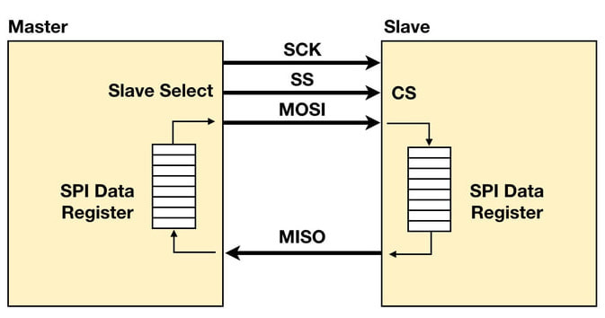
Unlike a standard serial port, SPI is a synchronous protocol in which all transmissions are referenced to a common clock, generated by the master (processor). The receiving peripheral (slave) uses the clock to synchronize its acquisition of the serial bit stream. Many chips may be connected to the same SPI interface of a master. A master selects a slave to receive by asserting the slave’s chip select (also known as a slave select) input. A peripheral that is not selected will not take part in a SPI transfer.
SPI uses four main signals: Master Out Slave In (MOSI), Master In Slave Out (MISO), Serial CLocK (SCLK or SCK) and low-active Chip Select (CS) for the peripheral. Some processors (including the PIC24 used in the Scamp) have a dedicated chip select for SPI interfacing called Slave Select (SS). Generally, chip selects are manually driven by software for a SPI transfer, whereas a slave select will be automatically controlled by the SPI module in the processor.
MOSI is generated by the master and is received by the slave. On some chips, MOSI is labeled simply as Serial In (SI) or Serial Data In (SDI). MISO is produced by the slave, but its transmission is triggered by the master. MISO is sometimes known as Serial Out (SO) or Serial Data Out (SDO) on some chips.
|
Masters and slaves each contain a serial shift register. The master starts a transfer of a byte by writing it to its SPI shift register. As the register transmits the byte to the slave on MOSI, the slave transfers the contents of its shift register back to the master on MISO.
In this way, the contents of the two shift registers are exchanged. Both a write and a read operation are performed with the slave simultaneously. SPI can therefore be a very efficient protocol. |
SPI data exchange
|
If only a write operation is desired, the master just ignores the data it receives. Conversely, if the master just wishes to read from a slave, it must transfer a dummy byte in order to initiate a slave transmission.
Some peripherals can handle multiple byte transfers, where a continuous stream of data is shifted from the master. Many memory chips with SPI interfaces work this way. With this type of transfer, the chip select for the SPI slave must remain low for the entire duration of the transmission. For example, a memory chip might expect a “write” command to be followed by four address bytes (starting address), then the data bytes to be stored. A single transfer may involve the shifting a kilobyte or more of information.
Other slaves need only a single byte (for example, a command byte for an analog-digital converter), and some (not all) even support being daisy-chained together:
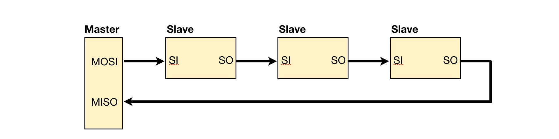
Some SPI slaves support daisy chaining
In this example, the master processor transmits three bytes out of its SPI interface. The first byte is shifted into slave A. As the second byte is transferred to slave A, the first byte is shifted out of slave A and into slave B. Similarly, as the third byte is shifted into slave A, the second byte is shifted into slave B, and the first byte is shifted into slave C. If the master wishes to read a result from slave A, it must again transfer a three-byte (dummy) sequence. This will move the byte from slave A into slave B, then into slave C, and finally into the master. In the process, the master also receives bytes from slave C and slave B in turn.
Note that daisy chaining won’t necessarily work with all SPI devices, especially ones that require multi-byte transfers (such as memory chips). Again, it’s a case of checking the peripheral chips’ datasheets carefully to determine what you can and can’t do. If the datasheet doesn’t explicitly mention daisy chaining, then it’s a fair bet that the device doesn’t support it.
SPI has four modes of operation, depending on clock polarity and clock phase. For low clock polarity, the clock (SCK) is low when idle, and toggles high during a transfer. When configured for high clock polarity, the clock is high when idle, and toggles low during a transfer.
The two clock phases are known as clock phase zero and clock phase one. For clock phase zero, MOSI and MISO outputs are valid on the rising edge of the clock (SCK) if the clock polarity is low. If the clock polarity is high, these outputs are valid on the falling edge of SCK, for clock phase zero.
Conversely, for clock phase one, the opposite is true. MOSI and MISO are valid on the falling edge of the clock if clock polarity is low. They are valid on the rising edge of the clock if the clock polarity is high.
Interfacing to A Single SPI Peripheral
|
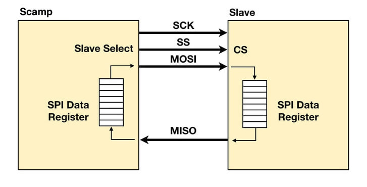
The PIC24 processor used in your Scamp has four SPI modules. The Scamp3 has dedicated pins for the SPI1 module, and provides Forth support for this module. (If needed, you can map the other SPI modules to the I/O pins of the main connector. Refer to the PIC24 datasheet for more information.)
On restart, the Scamp3 is configured to be a SPI Master. |
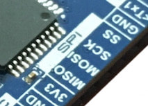
Scamp3 SPI Port
|
|
To interface a Scamp3 to a SPI peripheral, connect MOSI to the peripheral's data input (SDI, DI or MOSI). Connect MISO to the peripheral's data output (SDO, DO or MISO). Connect SCK to the clock input of the peripheral. The peripheral will have a CS input. If the peripheral is the only SPI device connected to your Scamp3, wire SS to CS, otherwise use a general purpose output for CS. You're ready to go.
|
Some SPI devices are very simple to use, others may have a complicated protocol. Be sure to read the peripheral's datasheet carefully to understand how to use the device with your Scamp.
Select SPI Clock Polarity
At reset/startup, the default polarity for the SPI clock (SCK) is high-active (low when idle). Some SPI peripherals require a low-active clock (high when idle).
To change SCK to be low-active (idle is high):
spiclk-
To change SCK to be high-active (idle is low):
spiclk+
The clock polarity can be changed as required for each peripheral.
Exchanging data with a SPI Peripheral
The word spix (SPI eXchange) takes a value from the stack, transmits this on the SPI interface, and in turn receives a value back from the SPI peripheral being accessed. In this example, the value $55 is transmitted to a peripheral, and the value returned from the peripheral is printed out:
$55 spix .
If your application only requires that you transmit data to a peripheral, then you can drop the unwanted value from the peripheral:
$55 spix drop
Conversely, if you want to read from a peripheral, then first put a dummy (don't care) value on the stack:
0 spix .
Setting the SPI Data Size
The default data size for a SPI transfer is 8 bits. So,
$1234 spix .
will only transmit $34 on the SPI interface, and will only receive 8 bits back.
If the peripheral can support 16-bit transfers, you can change the packet size to 16 bits:
If the peripheral can support 16-bit transfers, you can change the packet size to 16 bits:
#16 spisize
In 16-bit mode, the following will transmit the full 16 bits ($1234) to a SPI peripheral, and will receive 16 bits back.
$1234 spix .
If the peripheral can support 32-bit transfers, you can change the packet size to 32 bits:
#32 spisize
In 32-bit mode, spix will transmit 32 bits (two 16-bit values) to a SPI peripheral, and will receive 32 bits back.
To restore to 8-bit mode:
#8 spisize
Note that only 8, 16 and 32 are valid parameters for spisize. Other values are ignored.
Connecting Multiple SPI Peripherals
Each SPI peripheral has a chip select (CS) that must be sent low to select the device, and returned high at the end of the transaction. For multiple peripherals, use pins on the main connector (0..11) as outputs and connect one of these to each of the CS inputs on your peripherals. Do not use SS for a chip select in this instance as SS will go low for every SPI transaction.
For example, let's say we have a (hypothetical) SPI-based display and a SPI-based ADC. In this example, I'm assuming the ADC is a read-only device, and the LCD is write-only.
If we connect the display's CS to pin 2, and the ADC's CS to pin 3:
For example, let's say we have a (hypothetical) SPI-based display and a SPI-based ADC. In this example, I'm assuming the ADC is a read-only device, and the LCD is write-only.
If we connect the display's CS to pin 2, and the ADC's CS to pin 3:
2 constant LCD
3 constant ADC
LCD set \ set CS high (unselected) before configuring
ADC set \
LCD output \ configure pins as outputs on the Scamp3
ADC output
To read a value from the ADC and then write it to the LCD:
ADC clear \ ADC-CS active
0 spix \ send a dummy value and read back ADC result
ADC set \ ADC-CS inactive
LCD clear \ LCD-CS active
spix drop \ send value on stack and drop dummy read result
LCD set \ LCD-CS inactive
Note that real peripherals may require more complicated protocols than the trivial example above.
See the tutorial on Adding MRAM for a real-world example of using the SPI interface on a Scamp3.
Learn : Interfacing : SPI