CREATE : MEMORY : Adding MRAM
The MR25H256A (datasheet) is a serial, non-volatile, 32Kx8 magnetoresistive memory with a SPI Interface. MRAM is very similar to SRAM (static memory) in terms of operation, but it retains its data for 25 years without power and without battery backup. In this respect it is very much like flash. Unlike flash, operation is much faster and much simpler, since there is no need to erase pages of memory as is required with a flash device. With an MRAM, you just write data, and read it back later.
The MRAM requires power (3V3) and ground. MISO on the Scamp3 is connected to MISO on the MRAM. Similarly, MOSI on the Scamp3 goes to the MRAM's MOSI. And SCK is connected to SCK.
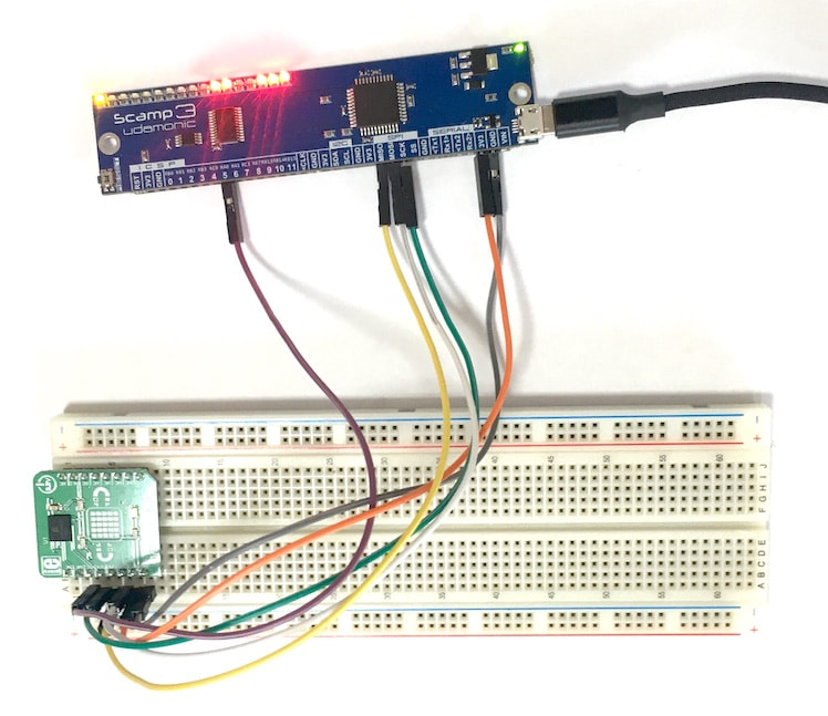
Scamp3 connected to a breadboard-mounted MRAM module
The MR25H256A is a little unusual when it comes to SPI. Unlike many other devices which have a fixed transfer size, this chip requires SPI transfers of different sizes in different contexts. Commands sent to the device are 8 bits wide, addresses are 16 bits, and data can be any number of bytes long. For example, to write a value to memory, first we send a WRITE command (8 bits), followed by the 16-bit start address, followed by the data. The chip select (CS) needs to go low at the start of a transaction, and remain low until the end. Therefore, we need to use a "manual" chip select rather than the automatically generated Slave Select (SS) from the Scamp. SS automatically goes high at the end of each write to the Scamp3 SPI module, which makes it inappropriate for the MRAM. We need a chip select we can send low at the start, and hold low until we are done. This can be easily achieved with one of the Scamp3 I/O pins. In this case, we choose pin 5 and connect this to CS on the MRAM, and define the following words to select and deselect the MRAM:
: select
#5 clear ;
: deselect
#5 set ;
On powerup, the MRAM is locked against writes. The following word puts the MRAM in write-enable ("wren") mode.
: mwren ( -- , write enable command )
select
#8 spisize \ 8 bit transfer for command
#6 spix drop \ send wren command
deselect
;
To initialize the chip select and enable writes, we create this word and run it:
: MRAMinit
deselect \ make sure pin 5 is set high
#5 output \ configure pin 5 as CS
mwren \ allow writes to MRAM
;
MRAMinit
The MRAM has a status register, and the following word will read that register and place the value on the stack.
: mstat ( -- status , get MRAM status )
#8 spisize \ 8 bit transfer
select
#5 spix \ send read-status command (5)
spix \ do another transfer to read status of MRAM
deselect
;
For normal use, you don't need to bother with the status register.
Next we define two words to write and read 16-bit values:
Next we define two words to write and read 16-bit values:
: m! ( value address -- , write value to MRAM address )
select
#8 spisize \ 8 bit transfer for command
#2 spix drop \ send write command
#16 spisize \ set for 16 bit address and data
spix drop \ send address from stack
spix drop \ send data
deselect
;
: m@ ( address -- value , read value from MRAM address )
select
#8 spisize \ 8 bit transfer for command
#3 spix drop \ send read command
#16 spisize \ set for 16 bit address and data
spix \ send 16 bit address
0 spix \ initiate read from MRAM
deselect
;
To test the interface, let's write the value $1234 to address $2000:
$1234 $2000 m!
To read back the value:
$2000 m@
... should result in $1234 on the stack.
You can expand on these basic words to write blocks of data to the MRAM.
You can expand on these basic words to write blocks of data to the MRAM.