CREATE : Adding an RTCC MODULE
This page shows how to add an RTCC module using a real-time clock calendar with the Texas Instruments BQ32000 (datasheet). The RTCC tracks seconds, minutes, hours, days of the week, days of the month, months and years. These are stored in the RTCC as binary coded decimal (BCD) values in hexadecimal format. Therefore, when writing to, or reading from, the RTCC, be sure to use hex format. This can be done be either placing Forth in hex mode first using the hex word, or by prefixing the numeric value with a $ to signify that it is hex value.
The RTCC supports battery backup of time and date. The schematic for the module is:
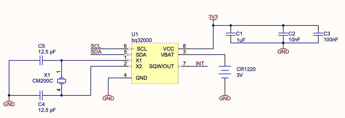
BQ3200 Schematic
The RTCC has an I2C address of $68. To make it easier to use, define a constant with this address:
$68 constant rtcc
The following words allow you to set the time:
: secs! ( seconds -- , set the seconds )
start
rtcc write drop
#0 send drop
send drop
stop
;
: mins! ( minutes -- , set the minutes )
start
rtcc write drop
#1 send drop
send drop
stop
;
: hours! ( hours -- , set the hours )
start
rtcc write drop
#2 send drop
send drop
stop
;
To set the date:
: day! ( day -- , set day of week, 1-7 are valid values )
start
rtcc write drop
#3 send drop
send drop
stop
;
: date! ( date -- , set date)
start
rtcc write drop
#4 send drop
send drop
stop
;
: month! ( month -- , set month )
start
rtcc write drop
#5 send drop
send drop
stop
;
: year! ( year -- , set year )
start
rtcc write drop
#6 send drop
send drop
stop
;
The year is stored in the RTCC as an 8-bit value, offset from the year 2000. Therefore only the last two digits of the year are significant. The upper 8 bits are ignored.
Once these words are defined, the time and date can be set thus:
Once these words are defined, the time and date can be set thus:
$7 month! ( July )
$23 date!
$19 year! ( 2019 )
$11 hours! $53 mins! $0 secs!
The following words allow the time and date to be read from the RTCC:
: secs@
start
rtcc write drop
#0 send drop
repstart
rtcc read drop
receive
nack
stop
;
: mins@
start
rtcc write drop
#1 send drop
repstart
rtcc read drop
receive
nack
stop
;
: hours@
start
rtcc write drop
#2 send drop
repstart
rtcc read drop
receive
nack
stop
;
: day@
start
rtcc write drop
#3 send drop
repstart
rtcc read drop
receive
nack
stop
;
: date@
start
rtcc write drop
#4 send drop
repstart
rtcc read drop
receive
nack
stop
;
: month@
start
rtcc write drop
#5 send drop
repstart
rtcc read drop
receive
nack
stop
;
: year@
start
rtcc write drop
#6 send drop
repstart
rtcc read drop
receive
nack
stop
;
To read back and display the current date and time, we can define the following word:
: today
base @ \ save the current base
hex \ change to hex
date@ 2 u.r
month@ 2 u.r
year@ 2 u.r
." :: "
hours@ 2 u.r
mins@ 2 u.r
secs@ 2 u.r
base ! \ restore previous base
;
(Remember that time and date are stored in hex BCD format, so we need to be in hex mode for the numbers to make sense.)
Calibrating the RTCC
No oscillator is perfect, and the 31.25 kHz oscillator driving the RTCC is no exception. The RTCC has a calibration value that can be applied to adjust the time as required. Refer to section 7.6.2.8 of the BQ32000 datasheet for more information. It's very important to understand the bit settings of the calibration register before modifying it.
The following word definitions allow you to read from, and write to, the calibration register:
The following word definitions allow you to read from, and write to, the calibration register:
: cal@ ( -- calregister , return calibration register )
start
rtcc write drop
#7 send drop
repstart
rtcc read drop
receive
nack
stop
;
: cal! ( n -- , set the calibration register )
start
rtcc write drop
#7 send drop
send drop
stop
;
The calibration register has a control bit that, when set, will output a 512 Hz test signal on the INT (interrupt) line. BE SURE TO DISABLE MODULE INTERRUPTS BEFORE USING THIS FEATURE. Connect an oscilloscope probe to the INT line to observe this test signal.
The following word definition will activate this test signal:
The following word definition will activate this test signal:
\ Enables the frequency test signal on INT (RB7)
\ ** disable module interrupts before using!
\ Connect an oscilloscope probe to RB7 to observe 512 Hz signal
: freqtest
cal@
%1000000 or
cal!
;
To use the freqtest word:
cal@ \ save current calibration settings to stack
dmi \ disable module interrupts
freqtest \ turn on test signal
\ perform measurements
cal! \ restore calibration settings to RTCC, turns off freqtest