Peripheral Pin Select (PPS)
The Microchip PIC24 processor used in your Scamp has a number of peripherals beyond those supported directly in the Scamp BSP. There are a large number of peripherals, and many different ways they can be configured - too many to make it practical to provide full support for every option in Forth. But, you can create your own Forth words to access the peripherals you want to use.
Because there are so many peripherals, Microchip use a system known as Peripheral Pin Select (PPS) to map (or remap) a peripheral to a given set of pins. The pins that are re-mappable are known as RP pins. Words such as analog, pwm, input and output in the Scamp dictionary use PPS under the hood to select a given pin. The registers that control PPS RP pins are RPINRxx for inputs and RPORxx for outputs.
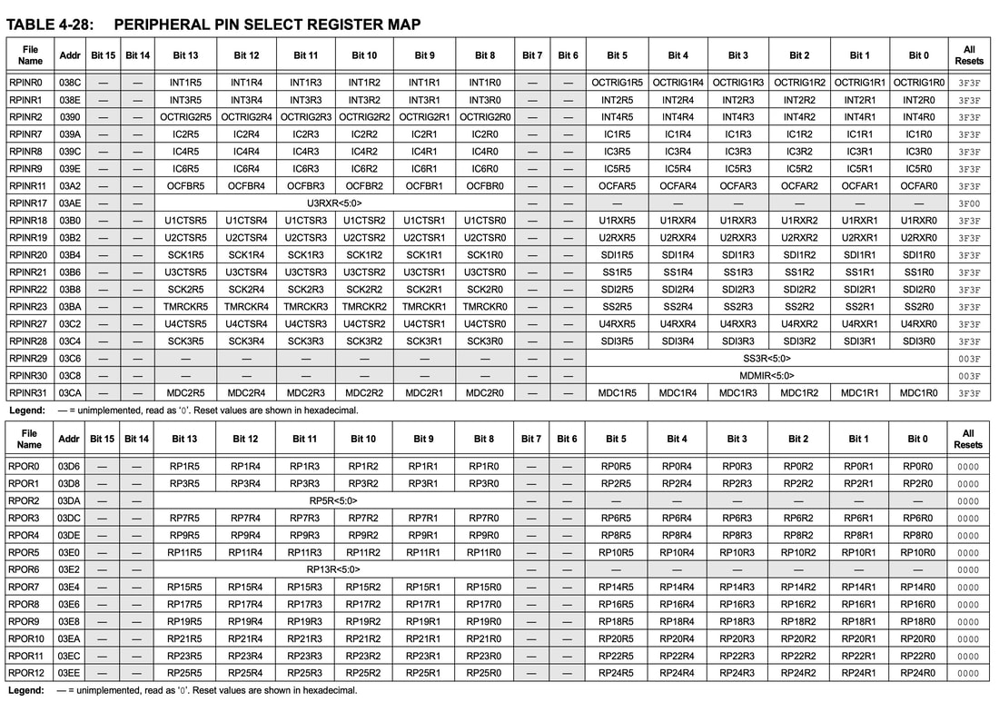
The following table (taken from the Microchip PIC24FJ128GB204 datasheet) shows you the addresses of the RP registers, and the corresponding peripheral bits under their control:
Because there are so many peripherals, Microchip use a system known as Peripheral Pin Select (PPS) to map (or remap) a peripheral to a given set of pins. The pins that are re-mappable are known as RP pins. Words such as analog, pwm, input and output in the Scamp dictionary use PPS under the hood to select a given pin. The registers that control PPS RP pins are RPINRxx for inputs and RPORxx for outputs.
The following table (taken from the Microchip PIC24FJ128GB204 datasheet) shows you the addresses of the RP registers, and the corresponding peripheral bits under their control:
Reference: Microchip PIC24 datasheet
It seems a bit daunting, but don't let it confuse you. Read the section of the datasheet for the peripheral(s) you want to use, and that will tell you which RP bits you need to configure in the PPS registers. For example, the 5 bits that select UART1 receiver (U1RX) can be found in the lower half of RPINR18 at address $03b0.
If you look at the schematic for your Scamp (found on the Resources page) you can see many of the pins of the PIC24 carry "RPx" in their name, and they can be remapped. (Pins that don't have RP can't be remapped.) Next to each pin in the schematic is a little grey box with a number in it, and that shows the number on the main connector associated with that pin. For example, on the Scamp3 main connector pin "7" is associated with "RP17" on the processor. So if you wanted to remap the main connector pin 7 to a peripheral (say UART4), you need to know that pin 7 is RP17.
If you look at the schematic for your Scamp (found on the Resources page) you can see many of the pins of the PIC24 carry "RPx" in their name, and they can be remapped. (Pins that don't have RP can't be remapped.) Next to each pin in the schematic is a little grey box with a number in it, and that shows the number on the main connector associated with that pin. For example, on the Scamp3 main connector pin "7" is associated with "RP17" on the processor. So if you wanted to remap the main connector pin 7 to a peripheral (say UART4), you need to know that pin 7 is RP17.
Inputs
To map an RP input to a given pin, you simply write the RP pin number to the appropriate bits of the appropriate register. The following table shows you the Scamp I/O pins and their corresponding RP number. (Note that not all pins are re-mappable.)
For example, let's say we want to map Input Capture 1 (IC1) to Scamp3's pin 6. IC1 is controlled by RPINR7 at address $039a. Pin 6 on the connector, from the schematic, is RP6. So to map IC1 to RP6, we simply write the value 6 to the lower half of RPINR7. Since we are working with the lower 8 bits, we can use c! to write the value.
6 $39a c!
Reading it back...
$39a @
hex .
... gives a value of $3f06. IC1 is now mapped to pin 6.
As another example, to map IC6 to Scamp pin 4, we first locate IC6 in the RPIN table and find that IC6 is the upper half of RPINR9, at address $039e. Now, pin 4 on the Scamp is RP14, so we need to write the decimal value 14 to the upper half of $039e. Since this is a 16 bit register, the upper half logically exists at address $039f, so that is the address to which we need to store the byte.
#14 $39f c!
And to confirm it worked,
$39e @
hex .
... returns a value of $e3f. The upper half of $e93 is $e, which is decimal 14. So IC6 is now mapped to pin 4 (RP14).
Outputs
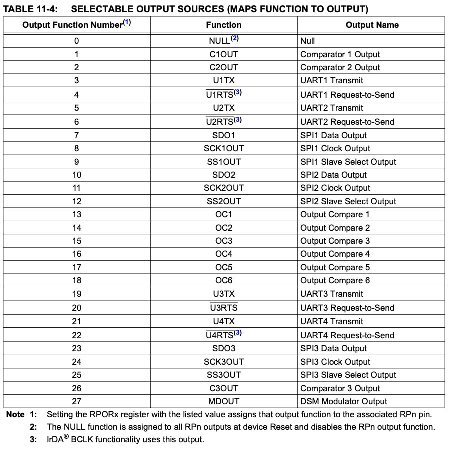
Peripheral outputs are handled slightly differently to inputs. For a given input, you assign a pin to an input. In contrast, for outputs you assign an output to a pin, by storing an output function number to a register controlling a particular pin. Refer to Table 4-28 (above) for the registers. The output function numbers are listed in Table 11-4 of the datasheet:
Reference: Microchip PIC24 datasheet
In the datasheet, you will read that the IO needs to be unlocked prior to configuration. This is performed when the Scamp starts up, so it's already done for you.
So, for example, let's say we want to use pin 10 of the Scamp for the output of the DSM Modulator. Pin 10 of the Scamp is RP13, and looking in Table 4-28 we can see that RP13 is controlled by the upper half of register RPOR6 at address $03e2. The output function code for the DSM Modulator output is #27, so to map the DSM Modulator output to the Scamp's pin 10 (RP13), we write #27 to the upper half of address $03e2. The upper half of $03e2 is at $03e3.
So, for example, let's say we want to use pin 10 of the Scamp for the output of the DSM Modulator. Pin 10 of the Scamp is RP13, and looking in Table 4-28 we can see that RP13 is controlled by the upper half of register RPOR6 at address $03e2. The output function code for the DSM Modulator output is #27, so to map the DSM Modulator output to the Scamp's pin 10 (RP13), we write #27 to the upper half of address $03e2. The upper half of $03e2 is at $03e3.
#27 $03e3 c!
To un-allocate a peripheral from a pin, simply write a 0 to the controlling register.
On a Scamp3, this is made easier for you with the word pin2por. This word takes a Scamp pin number and OFN from the stack, and assigns that output peripheral to the pin. For example, to assign the DSM output (OFN 27) to pin 2 on the Scamp3:
2 #27 pin2por